Home |
Map |
Projects |
Construction |
Soldering |
Study |
Components |
555 |
Symbols |
FAQ |
Links

Multimeters
Choosing | Digital |
Analogue | Voltage & Current |
Resistance | Diode | Transistor
Next Page: Resistance
Also See: Meters | Voltage and Current
 |
Liquid-Crystal Display
(LCD) |
Multimeters are very useful test instruments. By operating a multi-position switch on the
meter they can be quickly and easily set to be a voltmeter, an ammeter
or an ohmmeter. They have several settings (called 'ranges') for each type of
meter and the choice of AC or DC.
Some multimeters have additional features such as transistor testing and ranges for
measuring capacitance and frequency.
Choosing a multimeter
The photographs below show modestly priced multimeters which are suitable for general
electronics use, you should be able to buy meters like these for less than £15.
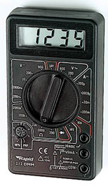
A digital multimeter is the best choice for your first multimeter, even the cheapest
will be suitable for testing simple projects.
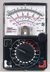
If you are buying an analogue multimeter make sure it has a high sensitivity of
20k /V
or greater on DC voltage ranges, anything less is not suitable for electronics.
The sensitivity is normally marked in a corner of the scale, ignore the lower AC value
(sensitivity on AC ranges is less important), the higher DC value is the critical one.
Beware of cheap analogue multimeters sold for electrical work on cars because their
sensitivity is likely to be too low.
/V
or greater on DC voltage ranges, anything less is not suitable for electronics.
The sensitivity is normally marked in a corner of the scale, ignore the lower AC value
(sensitivity on AC ranges is less important), the higher DC value is the critical one.
Beware of cheap analogue multimeters sold for electrical work on cars because their
sensitivity is likely to be too low.
Digital multimeters
All digital meters contain a battery to power the display so they use virtually no power
from the circuit under test. This means that on their DC voltage ranges they have a very
high resistance (usually called input impedance) of
1M
or more, usually 10M,
and they are very unlikely to affect the circuit under test.
Typical ranges for digital multimeters like the one illustrated:
(the values given are the maximum reading on each range)
- DC Voltage: 200mV, 2000mV, 20V, 200V, 600V.
- AC Voltage: 200V, 600V.
- DC Current: 200µA, 2000µA, 20mA, 200mA, 10A*.
*The 10A range is usually unfused and connected via a special socket.
- AC Current: None. (You are unlikely to need to measure this).
- Resistance: 200,
2000,
20k,
200k,
2000k,
Diode Test.
Digital meters have a special diode test setting because their
resistance ranges cannot be used to test diodes and other semiconductors.
Top of page | Choosing |
Digital | Analogue |
Voltage & Current | Resistance |
Diode | Transistor
Analogue multimeters
Analogue meters take a little power from the circuit under test to operate their
pointer. They must have a high sensitivity of at least
20k/V
or they may upset the circuit under test and give an incorrect reading.
See the section below on sensitivity for more details.
Batteries inside the meter provide power for the resistance ranges, they will last several
years but you should avoid leaving the meter set to a resistance range in case the leads
touch accidentally and run the battery flat.
Typical ranges for analogue multimeters like the one illustrated:
(the voltage and current values given are the maximum reading on each range)
- DC Voltage: 0.5V, 2.5V, 10V, 50V, 250V, 1000V.
- AC Voltage: 10V, 50V, 250V, 1000V.
- DC Current: 50µA, 2.5mA, 25mA, 250mA.
A high current range is often missing from this type of meter.
- AC Current: None. (You are unlikely to need to measure this).
- Resistance: 20,
200,
2k,
20k,
200k.
These resistance values are in the middle of the scale for each range.
It is a good idea to leave an analogue multimeter set to a DC voltage range such as 10V
when not in use. It is less likely to be damaged by careless use on this range, and
there is a good chance that it will be the range you need to use next anyway!
Sensitivity of an analogue multimeter
Multimeters must have a high sensitivity of at least
20k/V
otherwise their resistance on DC voltage ranges may be too low to avoid
upsetting the circuit under test and giving an incorrect reading. To obtain valid
readings the meter resistance should be at least 10 times the circuit
resistance (take this to be the highest resistor value near where the meter is connected).
You can increase the meter resistance by selecting a higher voltage range, but this may give
a reading which is too small to read accurately!
On any DC voltage range:
Analogue Meter Resistance = Sensitivity × Max. reading of range
e.g. a meter with 20k/V
sensitivity on its 10V range has a resistance of 20k/V
× 10V = 200k.
By contrast, digital multimeters have a constant resistance of at least
1M
(often 10M)
on all their DC voltage ranges. This is more than enough for almost all circuits.
Top of page | Choosing |
Digital | Analogue |
Voltage & Current | Resistance |
Diode | Transistor
Measuring voltage and current with a multimeter
- Select a range with a maximum greater than you expect the reading to be.
- Connect the meter, making sure the leads are the correct way round.
Digital meters can be safely connected in reverse, but an analogue meter may be damaged.
- If the reading goes off the scale: immediately disconnect and select a higher range.
Multimeters are easily damaged by careless use so please
take these precautions:
- Always disconnect the multimeter before adjusting the range switch.
- Always check the setting of the range switch before you connect to a circuit.
- Never leave a multimeter set to a current range (except when actually taking a reading).
The greatest risk of damage is on the current ranges because the meter has a
low resistance.
Measuring voltage at a point
When testing circuits you often need to find the voltages at various points,
for example the voltage at pin 2 of a 555 timer chip. This can seem confusing -
where should you connect the second multimeter lead?
 |
| Measuring voltage at a point. |
- Connect the black (negative -) lead to 0V, normally the negative
terminal of the battery or power supply.
- Connect the red (positive +) lead to the point
you where you need to measure the voltage.
- The black lead can be left permanently connected to 0V while you use the
red lead as a probe to measure voltages at various points.
- You may wish to fit a crocodile clip to the black lead of your multimeter
to hold it in place while doing testing like this.
Voltage at a point really means the voltage difference between that point and 0V
(zero volts) which is normally the negative terminal of the battery or power supply.
Usually 0V will be labelled on the circuit diagram as a reminder.
 |
Analogue Multimeter Scales
These can appear daunting at first but remember
that you only need to read one scale at a time!
The top scale is used when measuring resistance. |
Reading analogue scales
Check the setting of the range switch and choose an appropriate scale. For some ranges
you may need to multiply or divide by 10 or 100 as shown in the sample readings below.
For AC voltage ranges use the red
markings because the calibration of the scale is slightly different.
Sample readings on the scales shown:
DC 10V range: 4.4V (read 0-10 scale directly)
DC 50V range: 22V (read 0-50 scale directly)
DC 25mA range: 11mA (read 0-250 and divide by 10)
AC 10V range: 4.45V (use the red scale, reading 0-10)
If you are not familiar with reading analogue scales generally you may wish to see the
analogue display section on the general meters page.
Top of page | Choosing |
Digital | Analogue |
Voltage & Current | Resistance |
Diode | Transistor
Measuring resistance with a multimeter
To measure the resistance of a component it must not be connected in a circuit.
If you try to measure resistance of components in a circuit you will obtain false
readings (even if the supply is disconnected) and you may damage the multimeter.
The techniques used for each type of meter are very different so they are treated separately:
Measuring resistance with a DIGITAL multimeter
- Set the meter to a resistance range greater than you expect the resistance to be.
Notice that the meter display shows "off the scale" (usually blank
except for a 1 on the left). Don't worry, this is not a fault, it is correct - the
resistance of air is very high!
- Touch the meter probes together and check that the meter reads zero.
If it doesn't read zero, turn the switch to 'Set Zero' if your meter has
this and try again.
- Put the probes across the component.
Avoid touching more than one contact at a time or your resistance
will upset the reading!
Measuring resistance with an ANALOGUE multimeter
The resistance scale on an analogue meter is normally at the top, it is an unusual
scale because it reads backwards and is not linear (evenly spaced).
This is unfortunate, but it is due to the way the meter works.
- Set the meter to a suitable resistance range.
Choose a range so that the resistance you expect will be near the
middle of the scale. For example: with the scale shown below and an expected resistance of
about 50k
choose the × 1k range.
- Hold the meter probes together and adjust the control on the front of the meter which is
usually labelled
"0 ADJ"
until the pointer reads zero (on the RIGHT remember!).
If you can't adjust it to read zero, the battery inside the meter
needs replacing.
- Put the probes across the component.
Avoid touching more than one contact at a time or your resistance
will upset the reading!
|
Analogue Multimeter Scales
The resistance scale is at the top, note that it reads
backwards and is not linear (evenly spaced). |
Reading analogue resistance scales
For resistance use the upper scale, noting that it reads backwards and is
not linear (evenly spaced).
Check the setting of the range switch so that you know by how much to multiply the reading.
Sample readings on the scales shown:
× 10 range:
260
× 1k range:
26k
If you are not familiar with reading analogue scales generally you may wish to see the
analogue display section on the general meters page.
Top of page | Choosing |
Digital | Analogue |
Voltage & Current | Resistance |
Diode | Transistor
Testing a diode with a multimeter
The techniques used for each type of meter are very different so they are treated separately:
 |
| Diodes a = anode
k = cathode |
Testing a diode with a DIGITAL multimeter
- Digital multimeters have a special setting for testing a diode,
usually labelled with the diode symbol.
- Connect the red (+) lead to the anode and the
black (-) to the cathode.
The diode should conduct and the meter will display a value (usually the
voltage across the diode in mV, 1000mV = 1V).
- Reverse the connections. The diode should NOT conduct this way so the meter will
display "off the scale" (usually blank except for a 1 on the left).
Testing a diode with an ANALOGUE multimeter
- Set the analogue multimeter to a low value resistance range such as × 10.
- It is essential to note that the polarity of analogue multimeter
leads is reversed on the resistance ranges, so the black lead is positive
(+) and the red lead is negative (-)!
This is unfortunate, but it is due to the way the meter works.
- Connect the black (+) lead to anode and the
red (-) to the cathode.
The diode should conduct and the meter will display a low resistance
(the exact value is not relevant).
- Reverse the connections. The diode should NOT conduct this way so the meter
will show infinite resistance (on the left of the scale).
For further information please see the diodes page.
You may find it easier to test a diode with the
simple tester project.
Top of page | Choosing |
Digital | Analogue |
Voltage & Current | Resistance |
Diode | Transistor
Testing a transistor with a multimeter
 |
| Testing an NPN transistor |
Set a digital multimeter to diode test and an analogue multimeter
to a low resistance range such as × 10, as described above
for testing a diode.
Test each pair of leads both ways (six tests in total):
- The base-emitter (BE) junction should behave like a diode and
conduct one way only.
- The base-collector (BC) junction should behave like a diode and
conduct one way only.
- The collector-emitter (CE) should not conduct either way.
The diagram shows how the junctions behave in an NPN transistor.
The diodes are reversed in a PNP transistor but the same test procedure can be used.
For further information please see the transistors page.
You may find it easier to test a transistor with the
simple tester project.
Some multimeters have a 'transistor test' function, please refer to the
instructions supplied with the meter for details.
Top of page | Choosing |
Digital | Analogue |
Voltage & Current | Resistance |
Diode test | Transistor
Next Page: Resistance
| Studying Electronics
© VCampus 2013, The Electronics Club,
vcampus.co