Home |
Map |
Projects |
Construction |
Soldering |
Study |
Components |
555 |
Symbols |
FAQ |
Links

Soldering Guide
How to Solder | Advice for Components |
What is Solder? | Desoldering |
Burns
For information about soldering irons and other tools please see the
Tools Required page.
Download PDF version of this page
How to Solder
First a few safety precautions:
- Never touch the element or tip of the soldering iron.
They are very hot (about 400°C) and will give you a nasty burn.
- Take great care to avoid touching the mains flex with the tip of the iron.
The iron should have a heatproof flex for extra protection. An ordinary plastic
flex will melt immediately if touched by a hot iron and there is a serious
risk of burns and electric shock.
- Always return the soldering iron to its stand when not in use.
Never put it down on your workbench, even for a moment!
- Work in a well-ventilated area.
The smoke formed as you melt solder is mostly from the flux and quite irritating.
Avoid breathing it by keeping you head to the side of, not above, your work.
- Wash your hands after using solder.
Solder contains lead which is a poisonous metal.
If you are unlucky (or careless!) enough to burn yourself please read the
First Aid section.
Preparing the soldering iron:
- Place the soldering iron in its stand and plug in.
The iron will take a few minutes to
reach its operating temperature of about 400°C.
- Dampen the sponge in the stand.
The best way to do this is to lift it out the stand and hold it under a cold tap for
a moment, then squeeze to remove excess water. It should be damp, not dripping wet.
- Wait a few minutes for the soldering iron to warm up.
You can check if it is ready by trying to melt a little solder on the tip.
- Wipe the tip of the iron on the damp sponge.
This will clean the tip.
- Melt a little solder on the tip of the iron.
This is called 'tinning' and it will help the heat to flow from the iron's tip
to the joint. It only needs to be done when you plug in the iron, and occasionally
while soldering if you need to wipe the tip clean on the sponge.
You are now ready to start soldering:
- Hold the soldering iron like a pen, near the base of the handle.
Imagine you are going to write your name! Remember to never touch the hot element or tip.
- Touch the soldering iron onto the joint to be made.
Make sure it touches both the component lead and the track. Hold the tip there
for a few seconds and...
- Feed a little solder onto the joint.
It should flow smoothly onto the lead and track to form a volcano shape as shown
in the diagram. Apply the solder to the joint, not the iron.
- Remove the solder, then the iron, while keeping the joint still.
Allow the joint a few seconds to cool before you move the circuit board.
- Inspect the joint closely.
It should look shiny and have a 'volcano' shape. If not, you will need to reheat it
and feed in a little more solder. This time ensure that both the lead and track
are heated fully before applying solder.
If you are unlucky (or careless!) enough to burn yourself please read the
First Aid section.
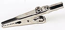
Using a heat sink
Some components, such as transistors, can be damaged by heat when soldering so if you are
not an expert it is wise to use a heat sink clipped to the lead between the joint and the
component body. You can buy a special tool, but a standard crocodile clip works just as
well and is cheaper.
Further information
For a much more detailed guide to soldering, including troubleshooting, please see the
Basic Soldering Guide
on the Everyday Practical Electronics Magazine website.
Top of page |
How to Solder |
Advice for Components |
What is Solder? |
Desoldering |
First Aid
Soldering Advice for Components
It is very tempting to start soldering components onto the circuit board straight
away, but please take time to identify all the parts first.
You are much less likely to make a mistake if you do this!
- Stick all the components onto a sheet of paper using sticky tape.
- Identify each component and write its name or value beside it.
- Add the code (R1, R2, C1 etc.) if necessary.
Many projects from books and magazines label the components with codes
(R1, R2, C1, D1 etc.) and you should use the project's parts list to find
these codes if they are given.
- Resistor values can be found using the resistor colour code
which is explained on our Resistors page.
You can print out and make your own Resistor Colour Code Calculator
to help you.
- Capacitor values can be difficult to find because there are
many types with different labelling systems! The various systems are
explained on our Capacitors page.
Some components require special care when soldering. Many must be placed the
correct way round and a few are easily damaged by the heat from soldering.
Appropriate warnings are given in the table below, together with other advice
which may be useful when soldering.
For more detail on specific components please see the
Components page or click on the component name in the table.
For most projects it is best to put the components onto the board in the order given below:
|
| Components
| Pictures
| Reminders and Warnings
|
| 1
| Chip Holders
(DIL sockets)
| 
| Connect the correct way round
by making sure the notch is at the correct end.
Do NOT put the ICs (chips) in yet.
|
| 2
| Resistors
| 
| No special precautions are needed with resistors.
|
| 3
| Small value capacitors
(usually less than 1µF)
| 
| These may be connected either way round.
Take care with polystyrene capacitors because they are
easily damaged by heat.
|
| 4
| Electrolytic capacitors
(1µF and greater)
| 
| Connect the correct way round.
They will be marked with a + or - near one lead.
|
| 5
| Diodes
| 
| Connect the correct way round.
Take care with germanium diodes (e.g. OA91) because they are
easily damaged by heat.
|
| 6
| LEDs
| 
| Connect the correct way round.
The diagram may be labelled a or + for anode and k or - for cathode;
yes, it really is k, not c, for cathode! The cathode is the short lead and there may
be a slight flat on the body of round LEDs.
|
| 7
| Transistors
| 
| Connect the correct way round.
Transistors have 3 'legs' (leads) so extra care is needed to ensure the
connections are correct.
Easily damaged by heat.
|
| 8
| Wire Links between points on the circuit board.
|  single core wire
| Use single core wire, this is one solid wire which is plastic-coated.
If there is no danger of touching other parts you can use tinned copper wire,
this has no plastic coating and looks just like solder but it is stiffer.
|
| 9
| Battery clips,
buzzers and other parts with their own wires
|
| Connect the correct way round.
|
| 10
| Wires to parts off the circuit board,
including switches,
relays,
variable resistors
and loudspeakers.
|  stranded wire
| You should use stranded wire which is flexible and plastic-coated.
Do not use single core wire because this will break when it is
repeatedly flexed.
|
| 11
| ICs (chips)
| 
| Connect the correct way round.
Many ICs are static sensitive.
Leave ICs in their antistatic packaging until you need them, then earth your hands
by touching a metal water pipe or window frame before touching the ICs.
Carefully insert ICs in their holders: make sure all the pins are lined up with
the socket then push down firmly with your thumb.
|
Top of page |
How to Solder |
Advice for Components |
What is Solder? |
Desoldering |
First Aid
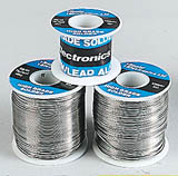
What is solder?
Solder is an alloy (mixture) of tin and lead, typically 60% tin and 40% lead.
It melts at a temperature of about 200°C.
Coating a surface with solder is called 'tinning' because of the tin content of solder.
Lead is poisonous and you should always wash your hands after using solder.
Solder for electronics use contains tiny cores of flux, like the wires inside a mains flex.
The flux is corrosive, like an acid, and it cleans the metal surfaces as the solder melts.
This is why you must melt the solder actually on the joint, not on the iron tip. Without
flux most joints would fail because metals quickly oxidise and the solder itself will not
flow properly onto a dirty, oxidised, metal surface.
The best size of solder for electronics is 22swg (swg = standard wire gauge).
Top of page |
How to Solder |
Advice for Components |
What is Solder? |
Desoldering |
First Aid
Desoldering
At some stage you will probably need to desolder a joint to remove or re-position a
wire or component. There are two ways to remove the solder:
 |
| Using a desoldering pump (solder sucker) |
1. With a desoldering pump (solder sucker)
- Set the pump by pushing the spring-loaded plunger down until it locks.
- Apply both the pump nozzle and the tip of your soldering iron to the joint.
- Wait a second or two for the solder to melt.
- Then press the button on the pump to release the plunger and suck the
molten solder into the tool.
- Repeat if necessary to remove as much solder as possible.
- The pump will need emptying occasionally by unscrewing the nozzle.
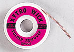
2. With solder remover wick (copper braid)
- Apply both the end of the wick and the tip of your soldering iron to the joint.
- As the solder melts most of it will flow onto the wick, away from the joint.
- Remove the wick first, then the soldering iron.
- Cut off and discard the end of the wick coated with solder.
After removing most of the solder from the joint(s) you may be able to remove the
wire or component lead straight away (allow a few seconds for it to cool).
If the joint will not come apart easily apply your soldering iron to melt the
remaining traces of solder at the same time as pulling the joint apart, taking
care to avoid burning yourself.
Top of page |
How to Solder |
Advice for Components |
What is Solder? |
Desoldering |
First Aid
First Aid for Burns
Most burns from soldering are likely to be minor and treatment is simple:
- Immediately cool the affected area under gently running cold water.
Keep the burn in the cold water for at least 5 minutes (15 minutes is recommended).
If ice is readily available this can be helpful too, but do not delay the initial
cooling with cold water.
- Do not apply any creams or ointments.
The burn will heal better without them. A dry dressing, such as a clean handkerchief,
may be applied if you wish to protect the area from dirt.
- Seek medical attention if the burn covers an area bigger than your hand.
To reduce the risk of burns:
- Always return your soldering iron to its stand immediately after use.
- Allow joints and components a minute or so to cool down before you touch them.
- Never touch the element or tip of a soldering iron unless you are certain it is cold.
Top of page |
How to Solder |
Advice for Components |
What is Solder? |
Desoldering |
First Aid
© VCampus 2013, The Electronics Club,
vcampus.co