Also see: LEDs | AC and DC |
Power Supplies
Example: ![]() Circuit symbol:
Circuit symbol: ![]()
 Diodes allow electricity to flow in only one direction. The arrow of the circuit symbol
shows the direction in which the current can flow. Diodes are the electrical version of
a valve and early diodes were actually called valves.
Diodes allow electricity to flow in only one direction. The arrow of the circuit symbol
shows the direction in which the current can flow. Diodes are the electrical version of
a valve and early diodes were actually called valves.
Ordinary diodes can be split into two types: Signal diodes which pass small currents of 100mA or less and Rectifier diodes which can pass large currents. In addition there are LEDs (which have their own page) and Zener diodes (at the bottom of this page).
 Diodes must be connected the correct way round, the diagram may be labelled a or
+ for anode and k or - for cathode (yes, it really is k, not c,
for cathode!). The cathode is marked by a line painted on the body.
Diodes are labelled with their code in small print, you may need a magnifying glass
to read this on small signal diodes!
Diodes must be connected the correct way round, the diagram may be labelled a or
+ for anode and k or - for cathode (yes, it really is k, not c,
for cathode!). The cathode is marked by a line painted on the body.
Diodes are labelled with their code in small print, you may need a magnifying glass
to read this on small signal diodes!
Small signal diodes can be damaged by heat when soldering, but the risk is small unless you are using a germanium diode (codes beginning OA...) in which case you should use a heat sink clipped to the lead between the joint and the diode body. A standard crocodile clip can be used as a heat sink.
Rectifier diodes are quite robust and no special precautions are needed for soldering them.
General purpose signal diodes such as the 1N4148 are made from silicon and have a forward voltage drop of 0.7V.
Germanium diodes such as the OA90 have a lower forward voltage drop of 0.2V and this makes them suitable to use in radio circuits as detectors which extract the audio signal from the weak radio signal.
For general use, where the size of the forward voltage drop is less important, silicon diodes are better because they are less easily damaged by heat when soldering, they have a lower resistance when conducting, and they have very low leakage currents when a reverse voltage is applied.
| Diode | Maximum Current |
Maximum Reverse Voltage |
| 1N4001 | 1A | 50V |
| 1N4002 | 1A | 100V |
| 1N4007 | 1A | 1000V |
| 1N5401 | 3A | 100V |
| 1N5408 | 3A | 1000V |
All rectifier diodes are made from silicon and therefore have a forward voltage drop of 0.7V. The table shows maximum current and maximum reverse voltage for some popular rectifier diodes. The 1N4001 is suitable for most low voltage circuits with a current of less than 1A.
Also see: Power Supplies
The diagram shows the operation of a bridge rectifier as it converts AC to DC. Notice how alternate pairs of diodes conduct.
Also see: Power Supplies
 |
 |
 |
 |
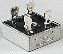 |
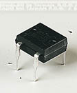
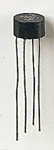
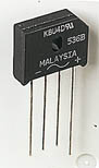
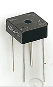
| Various types of Bridge Rectifiers
Note that some have a hole through their centre for attaching to a heat sink Photographs © Rapid Electronics | ||||
 Zener diodes are used to maintain a fixed voltage. They are designed to 'breakdown'
in a reliable and non-destructive way so that they can be used in reverse to maintain
a fixed voltage across their terminals. The diagram shows how they are connected, with
a resistor in series to limit the current.
Zener diodes are used to maintain a fixed voltage. They are designed to 'breakdown'
in a reliable and non-destructive way so that they can be used in reverse to maintain
a fixed voltage across their terminals. The diagram shows how they are connected, with
a resistor in series to limit the current.
Zener diodes can be distinguished from ordinary diodes by their code and breakdown voltage which are printed on them. Zener diode codes begin BZX... or BZY... Their breakdown voltage is printed with V in place of a decimal point, so 4V7 means 4.7V for example.
Zener diodes are rated by their breakdown voltage and maximum power: