Photographs © Rapid Electronics

Choosing a relay | Protection diodes | Reed relays | Advantages & disadvantages
|
| Circuit symbol for a relay |
|
|
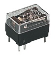
| Relays Photographs © Rapid Electronics |
|
| Relay showing coil and switch contacts |
Relays allow one circuit to switch a second circuit which can be completely separate from the first. For example a low voltage battery circuit can use a relay to switch a 230V AC mains circuit. There is no electrical connection inside the relay between the two circuits, the link is magnetic and mechanical.
The coil of a relay passes a relatively large current, typically 30mA for a 12V relay, but it can be as much as 100mA for relays designed to operate from lower voltages. Most ICs (chips) cannot provide this current and a transistor is usually used to amplify the small IC current to the larger value required for the relay coil. The maximum output current for the popular 555 timer IC is 200mA so these devices can supply relay coils directly without amplification.
Relays are usuallly SPDT or DPDT but they can have many more sets of switch contacts, for example relays with 4 sets of changeover contacts are readily available. For further information about switch contacts and the terms used to describe them please see the page on switches.
Most relays are designed for PCB mounting but you can solder wires directly to the pins providing you take care to avoid melting the plastic case of the relay.
The supplier's catalogue should show you the relay's connections. The coil will be obvious and it may be connected either way round. Relay coils produce brief high voltage 'spikes' when they are switched off and this can destroy transistors and ICs in the circuit. To prevent damage you must connect a protection diode across the relay coil.
The animated picture shows a working relay with its coil and switch contacts. You can see a lever on the left being attracted by magnetism when the coil is switched on. This lever moves the switch contacts. There is one set of contacts (SPDT) in the foreground and another behind them, making the relay DPDT.
The relay's switch connections are usually labelled COM, NC and NO:
| Relay coil current = | supply voltage |
| coil resistance |
 Transistors and ICs (chips) must be protected from the brief high voltage 'spike' produced
when the relay coil is switched off. The diagram shows how a signal diode
(eg 1N4148) is connected across the relay coil to provide this protection.
Note that the diode is connected 'backwards' so that it will normally not conduct.
Conduction only occurs when the relay coil is switched off, at this moment current tries to
continue flowing through the coil and it is harmlessly diverted through the diode.
Without the diode no current could flow and the coil would produce a damaging high voltage
'spike' in its attempt to keep the current flowing.
Transistors and ICs (chips) must be protected from the brief high voltage 'spike' produced
when the relay coil is switched off. The diagram shows how a signal diode
(eg 1N4148) is connected across the relay coil to provide this protection.
Note that the diode is connected 'backwards' so that it will normally not conduct.
Conduction only occurs when the relay coil is switched off, at this moment current tries to
continue flowing through the coil and it is harmlessly diverted through the diode.
Without the diode no current could flow and the coil would produce a damaging high voltage
'spike' in its attempt to keep the current flowing.
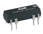 |
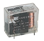
| Reed Relay Photograph © Rapid Electronics |
Reed relays generally have higher coil resistances than standard relays
(1000![]() for example)
and a wide range of supply voltages (9-20V for example). They are capable of switching
much more rapidly than standard relays, up to several hundred times per second; but they
can only switch low currents (500mA maximum for example).
for example)
and a wide range of supply voltages (9-20V for example). They are capable of switching
much more rapidly than standard relays, up to several hundred times per second; but they
can only switch low currents (500mA maximum for example).
The reed relay shown in the photograph will plug into a standard 14-pin DIL socket ('chip holder').
For further information about reed switches please see the page on
switches.
Advantages of relays:
Disadvantages of relays: