
Audio & communication: Jack | Phono | Coax | BNC | DIN | D | IDC & RJ45
Cables: Single-core |
Stranded | Signal |
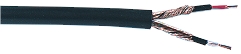
Screened | Co-axial |
Mains flex
|
|
| Photographs © Rapid Electronics |
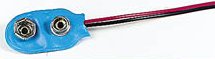
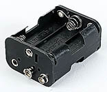
Many small electronic projects use a 9V PP3 battery but if you wish to use the project for long periods a better choice is a battery holder with 6 AA cells. This has the same voltage but a much longer battery life and it will work out cheaper in the long run.
Larger battery clips fit 9V PP9 batteries but these are rarely used now.
 |
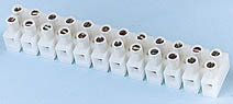 |
| PCB terminal block |
Terminal block Photographs © Rapid Electronics |
PCB mounting terminal blocks provide an easy way of making semi-permanent connections
to PCBs. Many are designed to interlock to provide more connections.
 |
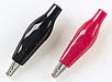 |
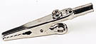
| Crocodile clips Photographs © Rapid Electronics | |
 | |
 | |
|
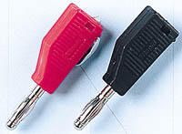
4mm terminal |
 |
 | |
| Photographs © Rapid Electronics | |
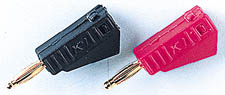
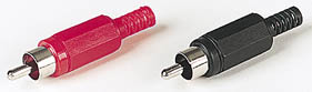
Plugs
Plugs may have a screw or solder terminal to hold the cable.
Check if you need to thread the cable through the cover before connecting it.
Some plugs, such as those illustrated, are 'stackable' which means that they
include a socket to accept another plug, allowing several plugs to be connected
to the same point - a very useful feature for test leads.
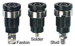
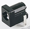
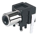
Sockets
These are usually described as 'panel mounting' because they are designed
to be fitted to a case. Most sockets have a solder contact but the picture shows other
options. Fit the socket in the case before attaching the wire otherwise you will be unable
to add the mounting nut.
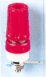
Terminals
In addition to a socket these have provision for attaching a wire
by threading it through a hole (or wrapping it around the post) and tightening the
top nut by hand. They usually have a threaded stud to fit a solder tag inside the case.
 |
| Photograph © Rapid Electronics |
 |
 |
| Photographs © Rapid Electronics | |
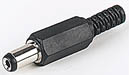
Miniature versions with a 1.3mm diameter plug are used where small
size is essential, such as for personal cassette players.
 |
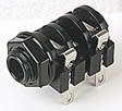 |
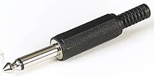
| ¼" (6.3mm) jack plug and socket | |
 |
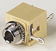 |
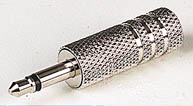
| 3.5mm jack plug and socket | |
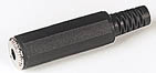 | |
| 3.5mm jack line socket (for fitting to a cable) Photographs © Rapid Electronics | |
Screened plugs have metal bodies connected to the COM contact. Most connections are soldered, remember to thread cables through plug covers before soldering! Sockets are designed for PCB or chassis mounting.
¼" plug connections are similar to those for 3.5mm plugs shown below. ¼" socket connections are COM, R and L in that order from the mounting nut, ignore R for mono use. Most ¼" sockets have switches on all contacts which open as the plug is inserted so they can be used to isolate internal speakers for example.
The connections for 3.5mm plugs and sockets are shown below. Plugs have a lug which should
be folded down to grip the cable's insulation and increase the strength of the joint.
3.5mm mono sockets have a switch contact which can be used to switch off an internal speaker
as the plug is inserted. Ignore this contact if you do not require the switching action.
 |
| 3.5mm jack plug and socket connections (the R connection is not present on mono plugs) |
L = left channel signal
R = right channel signal
COM = common (0V, screen)
Do not use jack plugs for power supply connections because the
contacts may be briefly shorted as the plug is inserted.
Use DC power connectors for this.
 |
 |
| Photographs © Rapid Electronics |
 |
| Construction of a screened cable |
 |
 |
| Photographs © Rapid Electronics | |
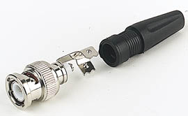 |
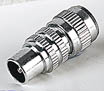
| BNC plug, photograph © Rapid Electronics |
Plugs and sockets are rated by their impedance
(50![]() or 75
or 75![]() )
which must be the same as the cable's impedance. If the connector and cable impedances are
not matched the signal will be distorted because it will be partly reflected at the
connection, this is the electrical equivalent of the weak reflection which occurs
when light passes through a glass window.
)
which must be the same as the cable's impedance. If the connector and cable impedances are
not matched the signal will be distorted because it will be partly reflected at the
connection, this is the electrical equivalent of the weak reflection which occurs
when light passes through a glass window.
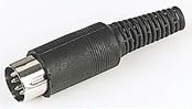 |
| DIN plug |
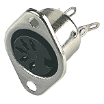 |
| 5 way 180° DIN socket (chassis mounting) |
| Photographs © Rapid Electronics |
Plastic covers of DIN plugs (and line sockets) are removed by depressing the retaining lug with a small screwdriver. You may also need small pliers to extract the body from the cover but do not pull on the pins themselves to avoid damage. Remember to thread the cable through the cover before starting to solder the connections!
Soldering DIN plugs is easier if you clamp the insert with the pins. Wires should be pushed into the hollow pins - first 'tin' the wires (coat them with a thin layer of solder) then melt a little solder into the hollow pin and insert the wire while keeping the solder molten. Take care to avoid melting the plastic base, stop and allow the pin to cool if necessary.
Mini-DIN connectors are used for computer equipment such as keyboards and mice but
they are not a good choice for general use unless small size is essential.
 |
 |
 |
| Photographs © Rapid Electronics |
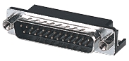
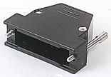
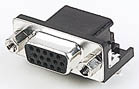
Note that covers (middle picture) are usually sold separately because both plugs and
sockets can be fitted to cables by fitting a cover to a chassis mounted connector.
PCB mounting versions of plugs and sockets are also available.
The contacts are usually numbered on the body of the connector, although you may need a
magnifying glass to see the very small markings. Soldering D-connectors requires a steady
hand due to the closeness of the contacts, it is easy to accidently unsolder a contact
you have just completed while attempting to solder the next one!
 |
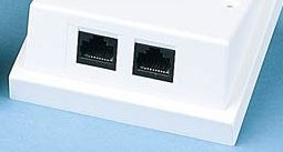 |
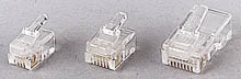
| Photographs © Rapid Electronics |
The 8-way RJ45 is the standard connector for modern computer networks. If you regularly use these you may be interested in our network lead tester project.
Standard UK telephone connectors are similar in style but a slightly different shape.
They are called BT (British Telecom) connectors.
Typical specification: 1/0.6mm (1 strand of 0.6mm diameter), maximum current 1.8A.
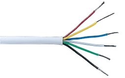
Typical specifications:
10/0.1mm (10 strands of 0.1mm diameter), maximum current 0.5A.
7/0.2mm (7 strands of 0.2mm diameter), maximum current 1.4A.
16/0.2mm (16 strands of 0.2mm diameter), maximum current 3A.
24/0.2mm (24 strands of 0.2mm diameter), maximum current 4.5A.
55/0.1mm (55 strands of 0.1mm diameter), maximum current 6A, used for test leads.
 |
| Photograph © Rapid Electronics |
| Screened cable (mono) |
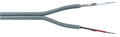 |
| Screened cable (stereo) |
 |
| Screened cable (stereo) |
| Photographs © Rapid Electronics |
|
| Construction of a screened cable |
| Photograph © Rapid Electronics |
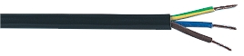 |
| Photograph © Rapid Electronics |
Mains flex is sometimes used for low voltage circuits which pass a high current,
but please think carefully before using it in this way. The distinctive colours of mains
flex should act as a warning of the mains high voltage which can be lethal; using mains
flex for low voltage circuits can undermine this warning.