
LDR | Thermistor |
Piezo transducer | Loudspeaker |
Buzzer & Bleeper | Inductor (coil)
|
| Photograph © Rapid Electronics |
|
| circuit symbol |
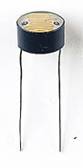
A multimeter can be used to find the resistance in darkness and bright light, these are the typical results for a standard LDR:
An LDR may be connected either way round and no special precautions are required
when soldering.
 | |
| Photograph © Rapid Electronics | |
| circuit symbol | |
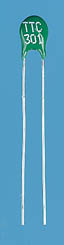
A multimeter can be used to find the resistance at various temperatures, these are some typical readings for example:
A thermistor may be connected either way round and no special precautions are required
when soldering. If it is going to be immersed in water the thermistor and its
connections should be insulated because water is a weak conductor; for example they
could be coated with polyurethane varnish.
 |
| Photograph © Rapid Electronics |
 |
| circuit symbol |
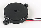
Piezo transducers require a small current, usually less than 10mA, so they can be connected directly to the outputs of most ICs. They are ideal for buzzes and beeps, but are not suitable for speech or music because they distort the sound. They are sometimes supplied with red and black leads, but they may be connected either way round. PCB-mounting versions are also available.
Piezo transducers can also be used as input transducers for detecting sudden
loud noises or impacts, effectively behaving as a crude microphone.
 |
| Photograph © Rapid Electronics |
 |
| capacitor in series to block DC |
 |
| circuit symbol |
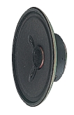
Most circuits used to drive loudspeakers produce an audio (AC) signal which is combined with a constant DC signal. The DC will make a large current flow through the speaker due to its low resistance, possibly damaging both the speaker and the driving circuit. To prevent this happening a large value electrolytic capacitor is connected in series with the speaker, this blocks DC but passes audio (AC) signals. See capacitor coupling.
Loudspeakers may be connected either way round except in stereo circuits when the + and - markings on their terminals must be observed to ensure the two speakers are in phase.
Correct polarity must always be observed for large speakers in cabinets because the cabinet may contain a small circuit (a 'crossover network') which diverts the high frequency signals to a small speaker (a 'tweeter') because the large main speaker is poor at reproducing them.
Miniature loudspeakers can also be used as a microphone and they work surprisingly
well, certainly good enough for speech in an intercom system for example.
 |
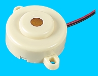 |
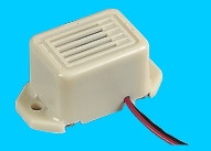
| Buzzer (about 400Hz) | Bleeper (about 3kHz) |
| Photographs © Rapid Electronics | |
| circuit symbol |  |
Buzzers have a voltage rating but it is only approximate, for example 6V and 12V buzzers can be used with a 9V supply. Their typical current is about 25mA.
Bleepers have wide voltage ranges, such as 3-30V, and they pass a low current of about 10mA.
Buzzers and bleepers must be connected the right way round, their red lead is positive (+).
| Inductor (miniature) |
 |
| Ferrite rod Photographs © Rapid Electronics |
| circuit symbol |
Inductors are rarely found in simple projects, but one exception is the tuning coil
of a radio receiver. This is an inductor which you may have to make yourself by neatly
winding enamelled copper wire around a ferrite rod. Enamelled copper wire has very thin
insulation, allowing the turns of the coil to be close together, but this makes it
impossible to strip in the usual way - the best method is to gently pull the ends of
the wire through folded emery paper.
Warning: a ferrite rod is brittle so treat it like glass, not iron!
An inductor may be connected either way round and no special precautions are required
when soldering.